Festo Limit Switch Wiring Diagram

Festo Smt 8 Ps K Led 24 B 175436 Proximity Switch For T Slot Pnp

Festo Estructura De Un Sistema De Control Neumatico Youtube

All Kinds Of Electrical Linear Actuators Google Search With

Oz 5170 Festo Limit Switch Wiring Diagram Wiring Diagram

Solenoid Valve Working And Connection Practically Youtube

5 Pin Relay With Diode Wiring Diagram Electrical Circuit
Draw roller operated normally closed limit switch of last actuated position of cylinder 5.
Festo limit switch wiring diagram. But i am more interested in the schematic relations of ideological opposition the first mani festo. They can come in all different technologies such as inductive photoelectric and capacitive just to list a few although the sensor technology may differ all 3 wire sensors are wired the same a three wire sensor has 3 wires present. Semi rotary here dfpb 2 couplingfor power transmission 3 shaft of the. Wiring diagram 163141 festo user manual and quick start guide english measuring carrying.
Limit switch electrical actuated from the right 152915 1 1 festo didactic. 1 ea festo vietnam air cylinders part no. Draw relay 1 6. The limit switch attachment is supplied with a mounted mounting attachment.
Switch on time ms 1 3 1 0 switch off time ms 1 4 1 0 max. Align the shaft of the limit switch attachment so that it the coupling if applicable and the shaft of the semi rotary drive engage each other in the desired manner example see fig 4. The two electrical limit switches pn 152906 for actuation from the left and pn 152915 for actuation from the right have the same symbol in the circuit diagram. Necessary i o triggering during synchronization via fct din4 output stage enable din5 controller enable din6 limit switch 0 din7 limit switch 1 din13 stop festo p be cmms st hw en 0903b.
Draw push button single cycle and detent switch multi cycle 4. Three wire sensors are used in various applications from detecting parts to locating position of the actual machine. Draw memory unit. In these page we also have variety of images available.
Options limit switch for pneumatically actuated diaphragm valves the 99p2 limit switchbox is a linear travel limit switch intended for use with linear style diaphragm valve actuators. Case operation manual english. We have 14 images about element molecule including images pictures photos wallpapers and more. If you are looking for element molecule you ve come to the right place.
Working and ats control panel wiring diagram duration. Page 28 required i o triggering during synchronization via mode switchover with 24 vdc frequency signals the connection plan shows the switch position in the active operating state. Limit switch operation limit switch purpose limit switch pin diagram pneumatic polarity. Festo quality at an attractive price.
Q w festo core product range covers 80 of your automation tasks worldwide. The switchbox contains two hermetically sealed switches for use in hazardous locations and the switches are self setting to reduce nuisance alarms and false trips.

Miniature Ball Valve For Compact Applications Valve Miniatures
Electro Pneumatic Circuit 1 Mechatronics Using Fluidsim For A
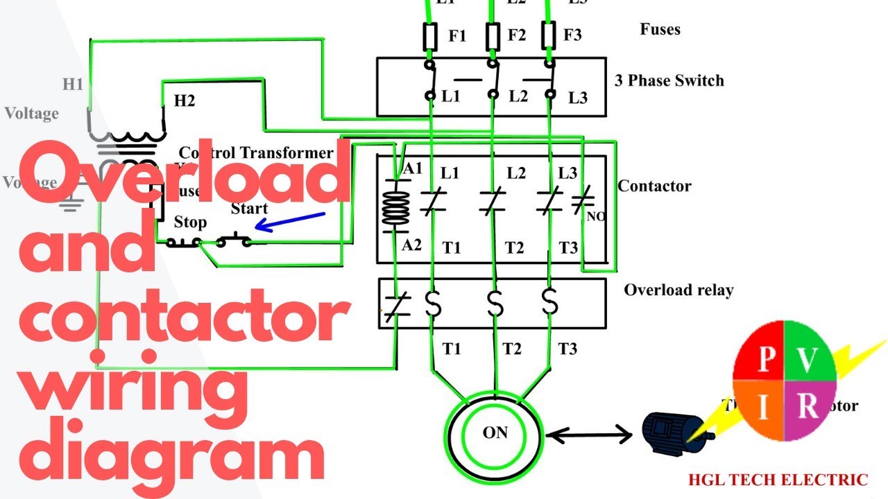
How To Wire A Contactor And Overload Start Stop 3 Phase Motor

How To Use A Pneumatic Cylinder Arduino Tutorial Youtube

Electro Pneumatic Circuit 4 Mechatronics Using Fluidsim For A B

How To Wire Discrete Dc Sensors To Plc Part 2 Youtube

How To Assign A Physical Position For A Limit Switch Pneumatics
Https Www Festo Com Rep En Nz Nz Assets Pdf Au Process Automation Overview Brochure 202018 Pdf

Electro Pneumatic Circuit 2 Mechatronics Using Fluidsim For A
Prof N Nagraj Pneumatic Control
Wiring Diagram For Outside Security Light Diagram Base Website
Arduino Solenoid Valve Circuit How To Control Water Flow With An

Fluidsim Mechatronics Electro Pneumatic Circuit Of Ab Delay
